3D Metrology Services – Tooling – Form Inspection of Cylindrical Surface
At EDM Intelligent Solutions, our high-resolution 3D scans of piece parts allow for form measurement down to the µm scale. Surface roughness measurement quantifies the frequency of peaks and valleys in the base material of a surface. With our 3D Metrology Services, we’re able to offer our customers in-depth, non-contact and non-destructive measurements of almost any shape, size, and form.
Below is an example of a form evaluation and surface roughness measurement using 3D profiles to extract roughness data from a injection mold insert. This is a four step process. The form inspection, surface roughness inspection, and 3D measurements of this component were completed using our MVi5 3D Metrology Center.
APPLICATION DETAILS
- Component – Injection Mold Insert
- Material – Hardened Tool Steel
- Metrology Services:
- Form Measurement
- Surface Roughness Measurement
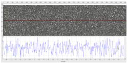
Step 1: Capture Data
Form Capture

Roughness Capture
![]()
Step 2: Extract critical data
Best Fit Cylinder

Step 3: Roughness Measurement
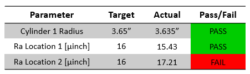
Step 4: Report Results
COMPETITIVE 3D METROLOGY, MEASUREMENT, AND INSPECTION SERVICES
Intelligent solutions to manufacturing and measurement challenges are what we do. Over the past 25 years, we’ve completed thousands of measurement and metrology projects. What differentiates EDM Intelligent Solutions 3D Metrology services from the competition is our unique understanding of each manufacturing process. The EDMIS metrology technicians and applications engineers support their colleagues in our tight tolerance CNC machine shop that produces ultra-precision components for customers every day. Harnessing this unique relationship with manufacturing, our metrology team has the experience needed to fully assist our customers leverage the measurements taken of their components to improve their manufacturing processes. We are confident that we can measure your most challenging components and work with you to fully understand what those measurements tell you about them. To learn more about how EDMIS can help you, contact our metrology team with your request for quote.